

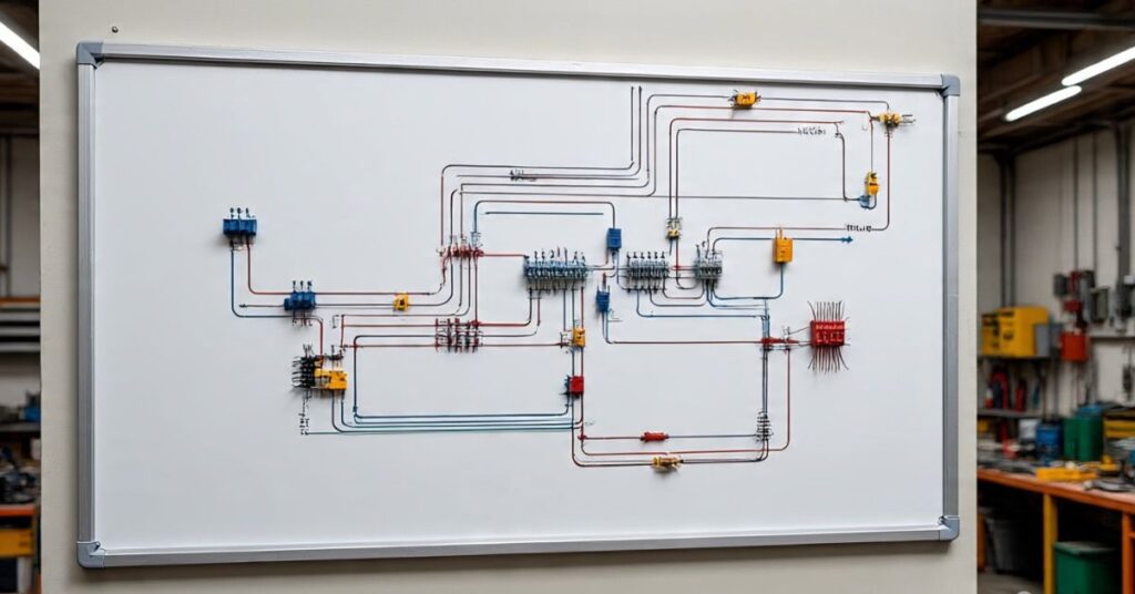
How to read an electrical wiring diagram is a skill every homeowner, electrician, and technician should master. These diagrams act like road maps for electricity. They guide you when installing, repairing, or troubleshooting any electrical system.
If you can read one properly, you will understand how current flows, where power connects, and what each symbol means. Without this knowledge, working with wires becomes guesswork, which can be unsafe and expensive. The good news is that wiring diagrams are not as hard as they look once you learn the basics step by step.
Why Wiring Diagrams Matter
The purpose of a wiring diagram is to show you the complete path of electrical current in a system. Unlike random sketches, these diagrams follow set rules so anyone who reads them can understand the same thing. If a light does not work, a wiring diagram helps you trace the power path and find out exactly where the fault lies.
In real life, electricians, car mechanics, and even engineers depend on wiring diagrams every day. A homeowner reading such a diagram before replacing a switch avoids mistakes that could cause short circuits or shocks. For this reason, wiring diagrams are not optional; they are essential.
Types of Electrical Drawings
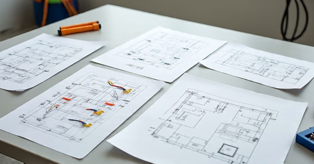
There are several forms of electrical drawings, and each serves a different purpose. A wiring diagram shows the actual connections between wires, devices, and components. A schematic is more about logic and shows how current flows but not the physical layout. A blueprint displays the larger structure of a building or system with wiring positions included.
Knowing the difference is important. For example, when installing a ceiling fan, you need a wiring diagram. When designing a control panel, you may look at a schematic. And when constructing a house, you rely on blueprints.
Read More : Can Solar Panels Be Installed on a Metal Roof?
Common Symbols and Notations

Every wiring diagram uses symbols that stand for switches, fuses, motors, and many other parts. Without knowing these symbols, you cannot follow the diagram. Luckily, these symbols are universal and explained in a legend or key on the diagram.
Different industries may have small variations. For example, automotive diagrams use battery symbols and ignition switches, while home wiring uses outlets and fixtures. Always check the legend before starting because missing one detail can cause a wrong connection.
Lines, Connections, and Paths
The lines you see on a wiring diagram are not random. They show how wires connect between devices. A solid line often means a direct connection. A dotted or dashed line usually shows an optional path, shield, or enclosure.
When two lines cross with a dot, that is a connection. If they cross without a dot, they are separate. Reading this carefully prevents errors when you try to wire or test a circuit.
You will like : Can You Paint Plastic Siding?
Power and Ground Fundamentals
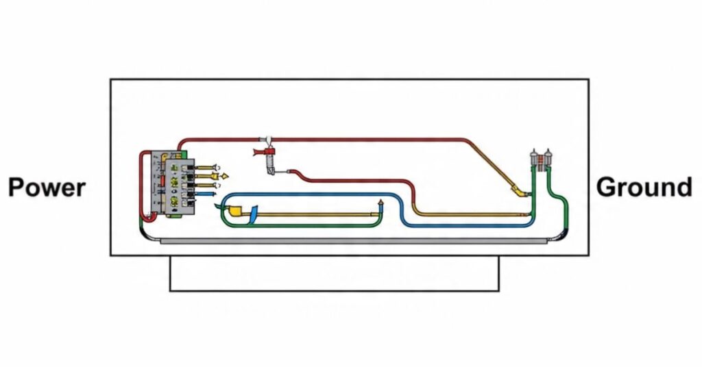
Every wiring diagram shows where power sources and ground connections are located. The power side is often marked with positive symbols or a voltage label. The ground is marked with the earth symbol or negative lines.
Grounding is not just another line. It protects against electric shock and stabilizes the system. Reading the ground points correctly is vital because a poor ground can cause flickering lights or damage to electronics.
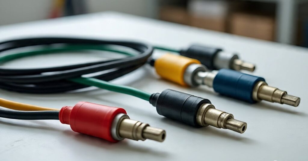
Wire Identification and Color Codes

Each wire in a wiring diagram has either a color code or a label. This is how you tell them apart. In North America, black or red wires usually carry power, while white is neutral and green is ground. Other countries use different colors.
Besides color, wires are often marked with numbers or letters. The diagram shows both the color and the label, so even if two wires look the same, you know which one goes where.
Circuit Flow and Logic

The key to how to read an electrical wiring diagram is to follow the path of current. Power enters from the source, travels through switches and loads, and returns to ground. The flow may look complicated, but step by step, it makes sense.
Understanding series circuits and parallel circuits is important. In a series, the current flows through each part one after another. In a parallel, current splits to power multiple devices at the same time.
Switches, Relays, and Controls
Switches are shown with open or closed positions. A simple single-pole single-throw switch is drawn as a break in the line. More advanced switches like double-pole double-throw have multiple paths.
Relays may look complex, but they are just switches controlled by coils. The diagram shows both the coil side and the contact side. Once you recognize these, relays become easy to read.
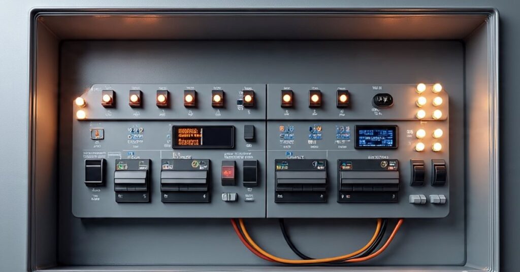
Fuses, Breakers, and Protection Devices
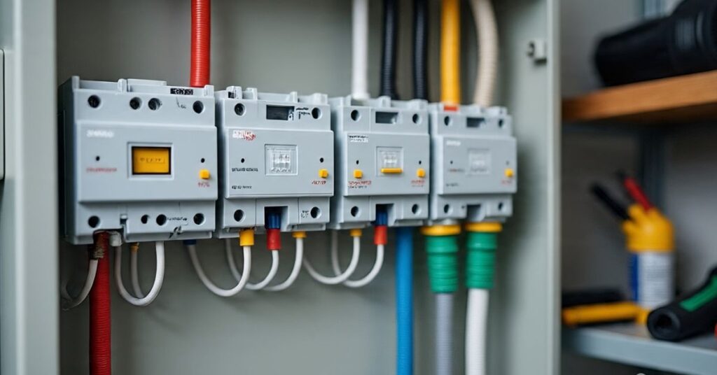
Every system uses protection devices. A fuse symbol shows a thin line with a break. A circuit breaker may appear as a box with a switch inside. These parts stop current when it becomes too high.
It is important to read not just the symbol but also the rating next to it. For example, a 15-amp fuse protects small circuits, while a 30-amp breaker handles bigger loads.
Loads and Devices

Loads are the devices that use electricity. In wiring diagrams, these are shown as motors, lamps, heaters, or electronics. Each has its own unique symbol.
Some loads are resistive, like heaters. Others are inductive, like motors. Understanding the difference matters because motors draw more current when they start, and that is shown in the diagram with extra connections.
Connectors, Terminals, and Harnesses
A connector symbol shows where two or more wires can be joined. Terminals are often numbered, so you know which wire goes into which pin.
Harnesses are bundles of wires running together. Instead of drawing every wire, the diagram may show them as one thick line with labels for each wire inside. This makes reading easier without losing detail.
Advanced Reading Skills

Once you know the basics, you must learn to separate control circuits from power circuits. Power circuits carry high current for devices like motors. Control circuits use small current for switches, sensors, or relays.
Diagrams also show test points. These are places where you can measure voltage or resistance with a multimeter. Knowing these helps in troubleshooting.
Tools and Techniques for Learning

Highlighting is a powerful method. Print the wiring diagram and use colored pens to trace each path. Following one wire from start to finish helps you focus.
Start with simple diagrams like a lamp and switch before moving to complex ones like car wiring or HVAC systems. The more you practice, the faster you will recognize patterns.
Safety Awareness in Diagram Reading
Reading wiring diagrams is safe, but applying them in real life involves risk. Always follow safety rules like wearing gloves, turning off breakers, and locking out circuits.
Never assume a wire is dead just because the diagram says so. Always test with a meter first. Safety is the most important step of all.
Practice and Real-World Application

The best way to learn is by applying the diagrams in real cases. For example, if a light does not work, follow the wiring diagram from power to switch to lamp. This step-by-step tracing reveals if the problem is a bad switch, a blown fuse, or a broken wire.
Case studies show that electricians who master wiring diagrams finish repairs faster and with fewer mistakes. Like reading a map, the more you do it, the more natural it feels.
| Circuit Type | Current Flow | Use Case |
| Series | Flows through each device | Old Christmas lights |
| Parallel | Splits into branches | Home outlets |
FAQs
What is the first step in reading a wiring diagram?
The first step is to read the legend and understand the symbols used.
How do you tell if wires connect in a diagram?
If lines cross with a dot, they connect. If they cross without a dot, they do not.
Why are wire colors important in a diagram?
Colors help you identify each wire’s role such as power, neutral, or ground.
Can I use a schematic instead of a wiring diagram?
Not always. A schematic shows logic but not the physical wire layout.
How do I practice reading diagrams safely?
Start with printed diagrams and use highlighting before touching real circuits.
Conclusion
Learning how to read an electrical wiring diagram makes electrical work safe, simple, and efficient. From understanding symbols to tracing circuits, each step builds your skill. By combining study with hands-on practice, you will soon read diagrams as easily as a map. With time, you will diagnose faults, install devices, and stay safe while doing it. Mastering this one skill opens the door to working confidently with any electrical system.